8 Different Types Of Gears and Their Applications
Today’s modern machinery is the most sophisticated and advanced in all of history. But it would not exist if it were not for the humble gear. Many people have pointed out that the wheel itself was not the greatest invention of all time until the axle was invented. Similarly, mechanical machines could not function without gears.
The earliest examples of gears date from China in the 4th century BC. The gears can be viewed at the Luoyang Museum of Henan Province.
In Europe, the earliest preserved gears date from around 150 BC. They were found in the Antikythera Mechanism, which was designed to calculate astronomical positions.
Gears also appeared in Roman Empire works from 50 AD and were mentioned in the Alexandrian school during the 3rd century BC. Most famously, Archimedes developed gears during that period.
Today, there are various types of gears that all have their own benefits and uses for numerous applications.
If you want to know more about the revolutionary devices known as gears, your first step should be to get to know the various types of gears that are used today. So, gear yourself up to find out more about eight of the most commonly used gears. But first things first. How are gears actually made?
Gear Machines
Gears enable machines to work. But machines enable gears to be manufactured. The best machinery for manufacturing gears is Computer Numerical Control gear machines. CNC gear machines can be used for cutting processes like milling, grinding, broaching, and hobbing, to make the gear types of your choice.


If you are looking to make gears, you should consider getting a CNC gear machine. A gear hobber is one machine that will come in very handy. It makes teeth by cutting into a workpiece.
The machine works by rotating the two spindles’ shafts and cutting into the material. Various materials can be used, including metal, wood, and plastic. You can get both vertical and horizontal gear hobbers.
Gear hobbers can typically create gears of up to ten feet. Hobbers are available in a wide range of sizes, such as light, standard, strong, and heavy-duty. Light hobbers are best for cutting diameters of up to 40 mm while heavy-duty ones are best for cutting diameters of up to 100 mm.
In addition to hobbers, there are CNC gear machines available such as broaching machines, bevel gear cutting machines, and gear shaving machines.
Buying a CNC gear machine does not have to cost the earth either. While new machinery can be on the costly side, these “second-hand” alternatives from leading brands are in full working order and just as good as brand-new machines, but less expensive. Now, let us take a look at some of the most commonly used gear types.
1. Spur Gears

Spur gears, also known as straight-cut gears, are the simplest type of gear and the type you are probably most aware of. A spur gear consists of a cylinder with teeth that project radially. The teeth are not straight-sided.
Instead, they are usually involute, and sometimes cycloidal. The edge of each tooth is straight, though, and is aligned parallel to the rotation axis. The gears must be fitted to parallel shafts if they are to mesh together properly. And with spur gears, no axial thrust is generated by the tooth loads.
This type of gear can be quite noisy when used at high speeds in machinery. That is because the teeth of spur gears abruptly meet a line of contact across their whole width, which causes some stress, resulting in noise. But spur gears are excellent for moderate and low-speed applications.
2. Helical Gears
Also known as dry-foxed gears, helical gears are more refined versions of spur gears. The key difference of a helical gear is its teeth are at an angle instead of being aligned to the rotation of the axis. Because the gear is a curved shape, the tooth looks like a section of a helix; hence the name.
Helical gears can mesh in either crossed or parallel orientations. Crossed orientations have non-parallel shafts. When the gears are in that configuration, they are sometimes called skew gears.
For a crossed or skew configuration, the gears must have a normal pitch and the same pressure angle. However, the handedness and the helix angle can vary. As for helical gears with parallel orientations, the shafts are simply parallel to one another.
Parallel-oriented helical gears are the most common form of helical gears. Each pair of teeth makes contact at a single point of the gear wheel at first and then gradually moves with curved contact across the face of the tooth and then recedes back until the teeth lose contact at a single point on the other side.
When using helical gears, you will notice how the angled teeth engage more gradually compared to the teeth of spur gears. Due to the gradual engagement of helical gear teeth, it means the gears run smoothly and quietly.
Therefore, helical gears are typically used for high-speed applications, unlike spur gears. Helical gears are also often used for applications in which large power transmission and noise abatement are important.
One disadvantage of the helical gear is the thrust along the axis of the gear means it must be accommodated by thrust bearings in the correct manner. However, that is not a problem for double helical gears.
In fact, it can be an advantage because it results in less axial thrust. Another disadvantage of helical gears is they have a greater chance of causing sliding friction between the teeth. Though, that problem can be treated by using a lubricant with additives.


3. Double Helical Gears

A double helical gear pretty much looks like two mirrored helical gears that are mounted together closely on the same axle. The gear is ideal for overcoming the issue of axial thrust that standard helical gears experience.
Double helical gears use a double set of teeth that are slanted in different directions. Due to the design of the helical gear, the arrangement cancels the total axial thrust. That is because each half of the double helical gear thrusts in opposing directions.
A double helical gear also reduces the potential need for thrust bearings. The only real issue with double helical gears is they are more difficult to maneuver because they have a more complex shape.
There are two potential arrangements for the rotational directions of helical gears. The first is a stable arrangement in which the gear’s faces are oriented so each axial force is directed to the gear’s center.
The second is an unstable arrangement. It involves both axial forces being directed away from the gear’s center. Regardless of which arrangement is used, the result is the same: the total axial force is zero when the gears align properly.
However, if the gears do become misaligned, the unstable arrangement creates a force that could lead to gear train disassembly. With a stable arrangement, a total corrective force is generated. And if the rotation direction is reversed, the direction of the axial thrusts is reversed as well, in which case, the stable configuration becomes unstable and vice versa.
There is also a special type of double helical gear called the herringbone gear. A herringbone gear does not have a groove in the middle like many double helical gears have. With a herringbone gear, the two mirrored gears are joined to make a V shape.
4. Cage Gears
Also known as lantern gears or lantern pinions, cage gears have teeth comprised of cylindrical rods that are parallel to the axle and arranged around it in a circle.
The gear somewhat resembles a lantern, hence the “lantern gear” alias. It also resembles a birdcage, hence the “cage gear” name. The assembly of the cage gear is held together via disks at each end, with the rod teeth and axle set between.
Cage gears are very efficient. They also do not get clogged up like other gears. Dirt can fall straight through instead of becoming trapped and increasing the gear’s wear.
Cage gears also have the advantage of being able to be manufactured with very simple tools due to the fact that the teeth do not need to be formed by milling or cutting. Instead, the method involves simply drilling holes and inserting the rods. Also, bear in mind that a cage gear should always be driven by a gearwheel. It should not be used as the driver.
The cage gear is most commonly used in clocks, although it is also used in other things like windmills. However, cage gears were not originally favored by conservative clockmaker.
It was only when cage gears were used for turret clocks, where working conditions were dirty and difficult, that the gears became more commonplace. Many traditional domestic clock movements use cage gears.
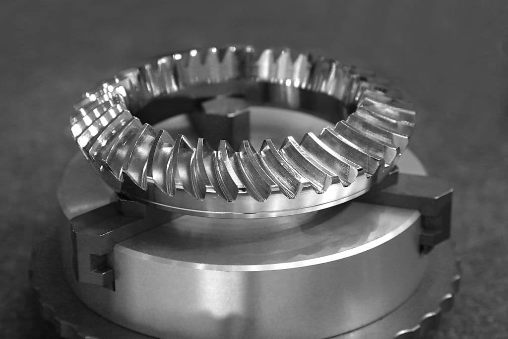
5. Bevel Gears
Imagine a circular cone with a cut-off tip. That is pretty much what a bevel gear looks like. When two bevel gears mesh together, their invisible vertices have to occupy the same point.
At that point, the axes intersect to form a non-straight angle between the shafts. That angle can be anything other than 180 or 0 degrees. When bevel gears have an equal number of shaft axes and teeth at 90 degrees, they are known as miter gears. Straight bevel gears are typically used at speeds of under 5 m/s.
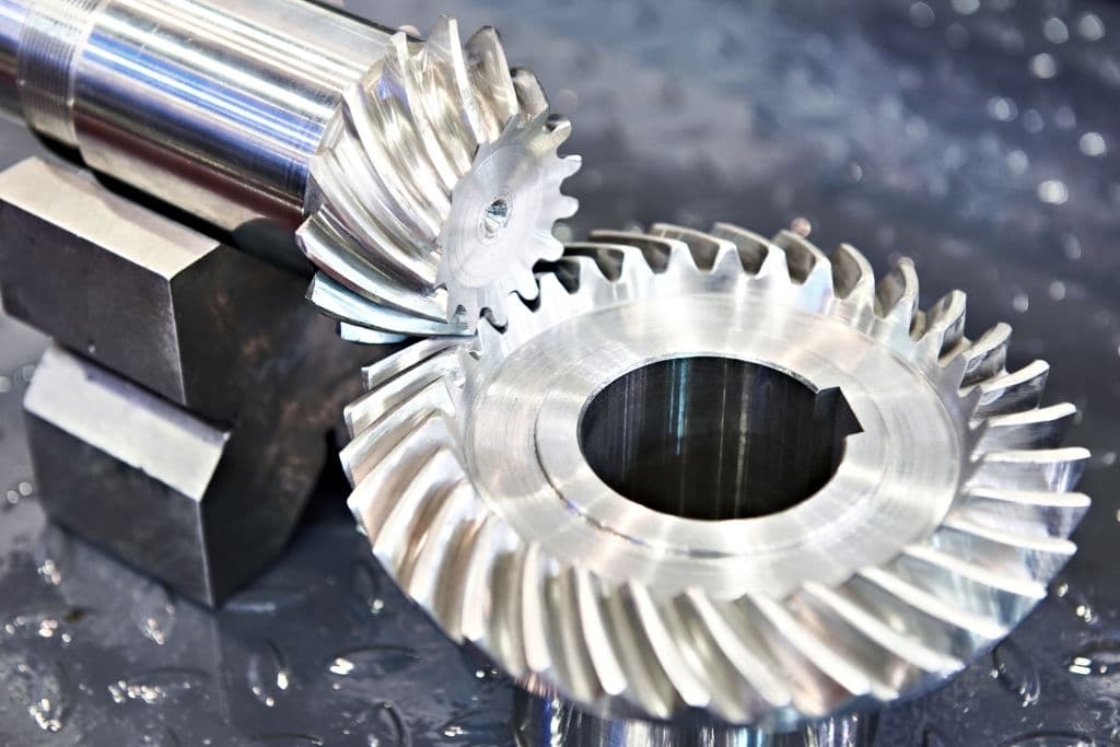
A specific type of bevel gear that is commonly used is the spiral bevel. Spiral bevels can be manufactured as circular arcs that have non-constant tooth depth or circular arcs with constant tooth depth.
Gleason spiral bevels are examples of the former and Curvex and Oerlikon are examples of the latter. Spiral bevel gears can also be manufactured as epicycloids with constant tooth depth, such as Klingelnberg Cyclo-Palloid gears.
6. Hypoid Gears
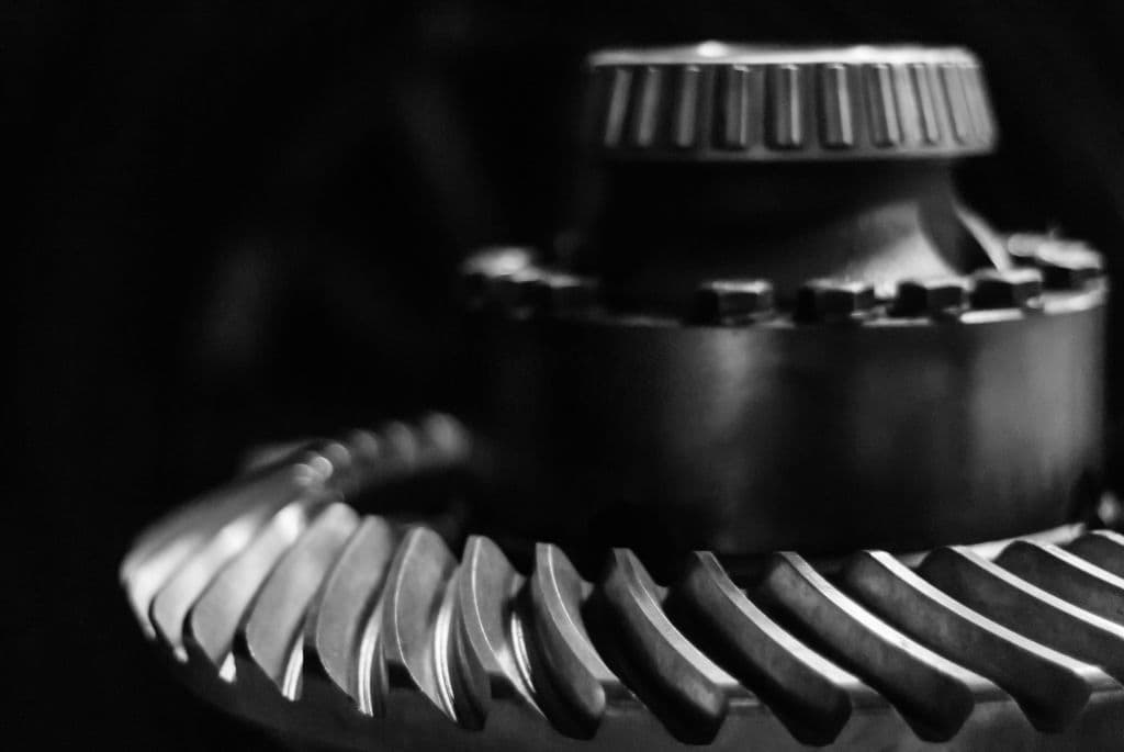
Hypoid gears are basically spiral bevel gears with one difference: the shaft axes do not intersect. Although hypoid gears look conical, they are actually hyperboloids of revolution compensating for the offset shaft. A hypoid gear is almost always operated with shafts of 90 degrees.
The contact between the hypoid gear’s teeth can be more gradual and smoother than with a spiral bevel gear, relative to the angling of the teeth and depending on the side that the shaft is offset to.
A hypoid gear also has a sliding action along the meshing teeth while it is rotating, therefore normally requiring some very hefty oil in order to stop it from being extruded from the touching tooth faces.
Compared to a spiral bevel gear, a hypoid gear’s pinion can be designed with fewer teeth. That results in the gear ratio being able to reach 60:1 or even higher. That is one reason why hypoid gears are most commonly used in motor vehicle drive trains. Non-hypoid gears are not suitable for motor vehicle drive trains because they generate too much vibration and noise.
7. Worm Gears
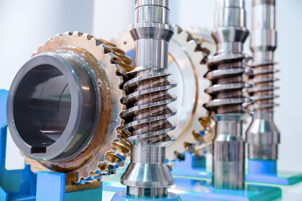
Worm-and-gear sets comprise of the “worm,” which resembles a screw, and the “worm wheel,” which is similar in appearance to a standard spur gear.
Using a worm-and-gear set is an easy and compact way to achieve a high torque and low-speed gear ratio. For instance, helical gears are typically limited to gear ratios of under 10:1.
With worm-and-gear sets, you can reach a gear ratio of up to 500:1. The only problem with using worm-and-gear sets is there is the potential for significant sliding action, which can slow down operations.
A worm gear is actually a type of helical gear. The main difference is a worm gear’s helix angle is typically larger and its body is longer in the axial direction.
Due to those attributes, worm gears have screw-like qualities. Also, unlike helical gears, worm gears have at least one tooth that persists for a full rotation around the helix. Worm gears can have just one tooth or several teeth.
Worm gears with one tooth are known as single-threads or single-starts. Gears with more than one tooth are known as multiple-threads or multiple-starts. The helix angle of worm gears is not usually given but the 90-degree lead angle minus the helix angle is given.
You should know that with a worm-and-gear set, the worm will always be able to drive the gear. But if the gear tries to drive the worm, it could be unsuccessful. It will not always be unsuccessful, but it can be; especially if the lead angle is small.
In that case, the gear’s teeth could lock against the worm’s teeth due to the force component that is circumferential to the worm not being sufficient to overcome the friction.
Worm gears can be right or left-handed. If you require medium to high power transmission, the tooth shape of the gear can be modified to gain more intimate contact.
That basically means the gears partially overlap. To do that, both gears must be made concave and joined at a saddle point. That is known as “double-enveloping,” or “cone-driving.” Self-locking worm-and-gear sets are available, as well.
That can be advantageous when you need to position a mechanism by turning the worm and hold that position. That kind of mechanism can be found in some musical instruments. Worms are often used in music boxes, too.
8. Magnetic Gears

This one is rather different from the other gears on this list. Instead of having teeth like standard gears, a magnetic gear uses magnets. As the two opposing magnets come closer, they repel. So, when they are placed on two rings, the two opposing magnets act like gear teeth.
Unlike the noisy, hard-contact backlash of spur gears, magnetic gears provide a springy backlash, resulting in the gears being able to apply pressure regardless of the relative angle. At the same time, magnetic gears provide the same motion ratio as traditional gears and are noise-free.
Magnetic gears are mostly used for very specific applications. For instance, a coupled magnetic gear can be used in a vacuum without the need for lubrication or in instances where there are hermetically sealed barriers.
Therefore, magnetic gears are ideal for use in hazardous environments where there is danger from things like explosive substance leaks. Magnetic gears have lots of other advantages. For instance, interchangeable ratios can be made within minutes instead of hours as with mechanical gears and wear is minimal due to the magnetic gears’ contact-free nature.
Typically, magnetic gear systems use permanent magnets but they can sometimes use electromagnets. The latter is usually reserved for specialized cases that involve changeable gear ratios.
The coupling of magnetic gears can be configured in several ways, including parallel input and output axes similar to standard spur gears. The cogs can also be intermeshed to improve the coupling.
Another configuration is in-lie axes that use flux coupling, in which an intermediate ferromagnetic cylinder enables a motion ratio thanks to the harmonic relationship between the input and output. There is no mechanical gear system that can do that because the two rotating gears are isolated from one another, only interacting magnetically.